Take a look at these models that will help you understand how networking works.
Why do we use models?
Most topics, such as music or science, use models in order to explain how something works. Models are useful because they help us conceptualise something that is complex. Computer networking is quite a complex topic, so using models will help us understand how it works.
The OSI model
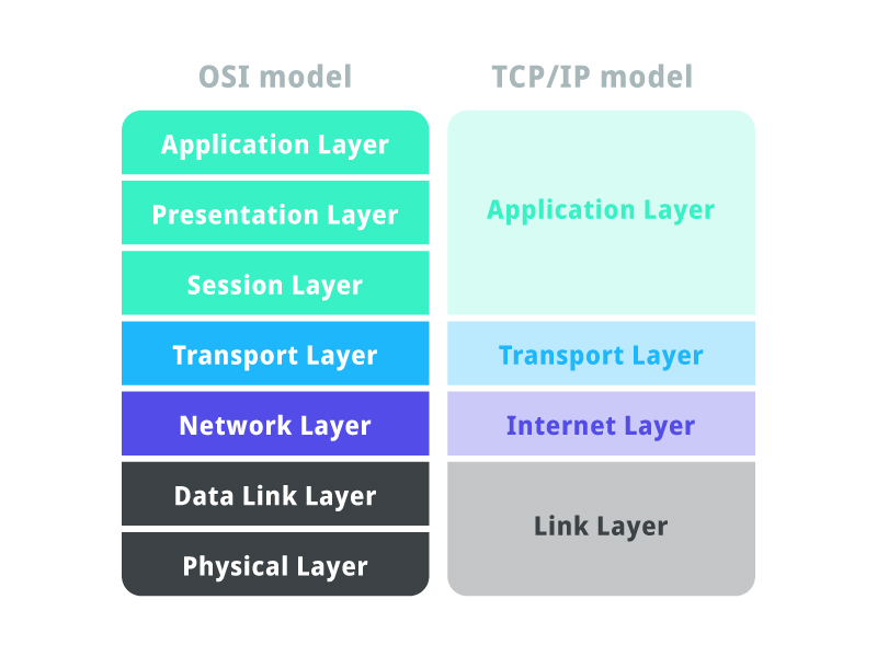
This seven-layer model helps us to conceptualise how networks work. It came out in the ’80s, so it’s pretty old, however, it is still an extremely useful reference when learning about networking. To the right of the OSI model is the TCP/IP model. It is very similar to the OSI model but has some differences. I won’t go into gory detail in this article. Here’s an explanation of each layer.
1 – Physical Layer
This is the easiest layer to understand because you can actually touch it! The physical layer is all the material stuff like cables and connectors. It also provides electrical functions such as line coding and modulation. In order for the services from the layers above the physical layer to work, the physical layer itself must be functioning; cables must be sitting in their sockets correctly etc.
2 – Data Link Layer
If you’ve ever heard of a Media Access Control address (MAC address) you’ll be pleased to know that this is where MACs sit in the whole process. This is the layer that actually transfers the data across the physical layer between the nodes of the network. When a computer sends data, there will be a source and a destination MAC address (like the names of two people talking to each other). Keep in mind, that MAC addresses don’t change (technically you can temporarily spoof your MAC address), they are statically programmed into the Network Interface Card (NIC). At this layer, we call the data that travels around, a frame.
Here’s an analogy:
Picture a road. There is a car travelling over this road. Inside the car, there are passengers. The physical layer is like the road; it provides the basic foundation that everything else works upon. The data link layer is like the car. It moves the passengers around and takes them where they want to go. Who are the passengers? They are the higher layers, that I’ll get to next.
The data link layer encapsulates the network layer. Encapsulating is like putting an outer envelope around something.
3 – Network Layer
I can almost bet that you’ve heard of an IP address. This is the layer where IP addresses do their thing. The network layer uses logical addresses, and IP addresses, to direct packets from source to destination. IP addresses can change, they are dynamic. MAC addresses are like your name – which shouldn’t change – IP addresses are like where you are – which could change. So, if you are on your home network, your computer will have some MAC address x and some IP address y. If you go to another network, your MAC address will be x and your IP address will be z. Notice the MAC stays the same no matter which network you’re a part of.
NOTE: this isn’t always the case. Sometimes the IP stays the same even on a different network. This has to do with private addressing (RFC1918), Network Address Translation, Locator/ID Separation Protocol etc.
Also…..Why do we have MAC addresses and IP addresses? If we’re trying to get data from some source to some destination, don’t we only need one address for the source and another for the destination?
There are a few answers to this. The way I would think of it is by imagining a letter being delivered from one place to another using the postal system. The letter will have a source name, a source street address, a destination name and a destination street address. The names are like MAC addresses and the street addresses are like IP addresses. Assuming that everyone had unique names, imagine if the postal system had to figure out where to send the letter next with just the person’s name! This would be like only using MAC addresses to deliver network data. It would be highly impractical to coordinate. Instead, the post office looks at the destination street address and figures out where to send it to. This is easier to do because street addresses are divided into things like states and postcodes. Now, when the letter arrives at the destination letterbox, the destination name can be used to distinguish exactly which member of the household the letter is for. This is like using the MAC to distinguish which individual computer the data is destined for.
So, to summarise, the IP address identifies which network the computer is part of, whereas the MAC address identifies the computer itself within the local network. By local, I am the network sitting behind a router.
The network layer encapsulates the transport layer.
4 – Transport Layer
Here lies TCP and UDP! Plus some other protocols like QUIC. At this layer and above, it starts to become harder to visualise what’s going on, because things get more logical. Essentially, at this layer, we’re providing communication between applications on different computers by using port numbers to figure out which applications are talking to each other. Think of a city with ports on the shore that send and receive goods. Imagine that each port is only used for a specific function, like importing cars. It would be useful for the large ships to know which port to send their packages to. With computers, it’s like the computer is the city and the ports are where applications sit. If data comes into the computer, how do we identify which application it’s for? This is exactly what port numbers do.
Some of the transport layer’s tasks:
- End-to-end connection
- Multiplexing and Demultiplexing
- Congestion Control
- Flow Control
- Error correction
Those terms might not mean much at this point, but basically, the transport layer takes data from upper layers that might be too large and chops it up into smaller chunks that are suitable to be transmitted. It also makes sure data received out of order is correctly reordered.
The transport layer encapsulates the application layer.
7 – Application Layer
What happened to layers 5 and 6? If you refer back to this image, you’ll notice that next to the OSI model is the TCP/IP model. Layers 5, 6 and 7 of the OSI model are simplified in the TCP/IP model as just ‘Application Layer’. This is because the services of establishing, maintaining and terminating sessions (OSI layer 5), and encoding/decoding compressing etc. (OSI layer 6) are often more easily understood as being part of just one ‘Application’ layer.
I prefer using a hybrid of both models:
- 5 – Application
- 4 – Transport
- 3 – Network
- 2 – Data Link
- 1 – Physical
We’re not as concerned with this layer when the data is ‘in-transit’, meaning it is being passed along by networking devices (routers, switches, wireless appliances etc.). This layer is more important at the start and end of the whole process, for example, the start is the first computer on which a user clicks a button on their web browser and the end being a server that processes the user’s request. Just think for a moment, if a bunch of data is coming into the computer, someone needs to figure out what to do actually do with it. This is what the application layer is concerned with. It is generally of more importance to software developers, whereas the lower layers, (1-4) are usually more important to networking professionals.
Tying Everything Together
Now that you are aware of the functions that are performed at each layer, let’s use an analogy to tie everything together.
Bob who lives in his home on 123 nicestreet, Brisbane 4000 QLD Australia is going to send a letter to Alive who lives in her home on 456 badstreet, Sydney 2000 NSW Australia. The letter simply says ‘Hello Alice’. Let’s walk through each step and compare it to if it were some computer, COM-A, on network NET-A, sending a file containing the words ‘Hello Alice’, to another computer, COM-B, on another network, NET-B.
- Bob constructs the letter – this is like the application layer on COM-A constructing the file.
- Bob puts the letter in an envelope. On the outside of the envelope, he writes the relevant information that will be used by the postal system – this is like how the transport, network, and data link layers add their information like port numbers, IP addresses and MAC addresses. Just as the postal offices use street addresses to figure out where the letter should go, networking devices like routers use digital addresses (IPs and MACs) to figure out where to ‘route’ the packets.
- Bob takes the letter to his local post office – this is like the network data from COM-A being sent to its local router for NET-A.
- The postal system handles the letter – this is like how the intermediary routers on Internet Service Providers (ISPs) between NET-A and NET-B route the packet.
- Alice’s local post office delivers the letter to her doorstep. This is like the local router on NET-B sending the network data to COM-B.
- Alice reads the letter. This is like COM-B’s application layer interpreting the file.
I hope you enjoyed reading this article and learned something new! Please consider leaving a comment if you have any questions / suggestions.